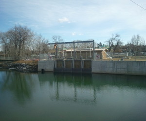
Fluid dynamics refers to the study of fluid in motion. It includes fluid moving through pipes, measurements with venturis and orifices, and other motion-related topics such as lift and drag, and pumps.
Reference
The field of fluid dynamics is a subcategory of fluid mechanics. It’s sibling is fluid statics.
In practice, the field of fluid dynamics has been divided into hydraulics and hydrodynamics.
- Hydraulics: The study of fluid flow and resistance in pipes and open channels.
- Hydrodynamics: The study of fluid behavior in a theoretical sense.
Hydrodynamics is like standard physics in that formulas derive from Newton’s laws of motion. Hydraulics often uses empirical formulas, curve fitting methods, and the like to produce engineering conclusions related to surface or pipe flow.
Conservation of Mass
In a fluid system, mass is always constant, regardless of the complexity of a pipeline system or orientation of flow. This simple concept extends to all fluid flow problems and results in the continuity equation:
$latex m_1 = m_2\newline\newline
\rho_1 A_1 v_1 = \rho_2 A_2 v_2$
Note: The fluid must be incompressible for this to apply.
Typical Velocities in Pipes
In a pipe network, friction is kept at acceptable levels by maintaining reasonable fluid velocities. The following table lists some maximum fluid velocities for various pipe systems.
| Fluid | Velocity | |
|---|---|---|
| ft/s | m/s | |
| Water: City water service | 2 – 5 | 0.6 – 1.5 |
| Water: boiler feed | 10 | 3 |
| Air: Compressor suction | 75 – 200 | 23 – 60 |
| Air: Compressor discharge | 100 – 250 | 30 – 75 |
| Refrigerant: Suction | 15 – 35 | 4.5 – 11 |
| Refrigerant: Discharge | 35 – 60 | 11 – 18 |
| Steam: Saturated | 65 – 100 | 20 – 30 |
| Steam: Superheated | 160 – 250 | 50 – 75 |
Laminar and Turbulent Flow
 Laminar flow is flow in a straight line. Turbulent flow is the opposite, i.e. rough and has many swirls. To determine which type of flow is present, you must calculate Reynold’s number, Re.
- If Re < 2,100, the flow is laminar
- If 2,100 < Re < 4,000, the flow is neither laminar nor turbulent. It is within the “transition zone.”
- If Re > 4,000, the flow is turbulent
Friction Losses
Energy loss due to friction is an ever present issue in the field of fluid dynamics. It is calculated using the following formula:
$latex h_f = \frac{fLv^2}{2Dg}&s=2$
Where:
hf = Head loss due to friction (ft or m)
f = friction factor
L = Length of pipe (ft or m)
v = Velocity (ft/s or m/s)
D = diameter of pipe (ft or m)
g = Acceleration due to gravity (ft/s2 or m/s2)
Head Loss
As fluid flows down a pipe or channel, it loses some of its energy. As well as friction losses, losses occur due to bends, changes in flow area, obstructions – essentially anything that impedes the flow from being in a straight line. This loss of energy will result in a loss of “elevation,” also called “stage” in open channel hydraulics.
Energy Grade Line vs. Hydraulic Grade Line
The energy of a fluid has three components.
- Kinetic (velocity)
- Potential
- Pressure
$latex E = \frac{v^2}{2} + z_2 g + \frac{p_1}{\rho}&s=2$
Where:
E = Energy
v = Velocity of the flow (ft/s or m/s)
z = Elevation relative to a reference (ft or m)
p = Pressure (lb/ft2 or Pa)
ρ = Density (lb/ft3 or kg/m3)
When the energy of the fluid is plotted along the length of the pipe or channel, it’s called the energy grade line (EGL). The EGL is the sum of the energy of the fluid. If the kinetic (first) term of the equation is omitted, it becomes the Hydraulic Grade Line (HGL). Thus the HGL is the potential energy within the fluid if it was not moving.
Pumps and Turbines
A pump adds energy to a fluid, and a turbine removes it. In most cases, pumps and turbines affect the pressure component of fluid energy only. Since energy must remain constant (Bernoulli) the energy added by a pump (or subtracted by a turbine) can be calculated based on the amount used by the pump or turbine.

Speak Your Mind