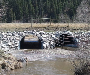
Tailwater is defined as the depth of flow in a channel immediately downstream of a drainage facility.
Since a drainage structure can create a constriction, the tailwater is usually a starting point, from which the resulting headwater is calculated.
Early in my career I was confused by this, because it would seem that building a structure on a watercourse would affect the downstream, not the upstream, channel. But the water will find a way to flow. If you block a stream, it will eventually overflow your blockage and return back to the same flow. The same thing goes for culverts that are too small. The effect on the downstream flow is only temporary, and thus the constant in design of drainage structures is the tailwater, not the headwater.
The only time this does not apply is if you are building a dam or some sort of major upstream storage facility. Then you are altering the watercourse’s ability to flow by storing it. But it has to be fairly significant to have an effect on the tailwater. It must store enough flow to remove flood peaks from the channel such that the design flow can be lowered.
But for a simple culvert or drainage structure, the tailwater can be calculated using manning’s equation with the average channel properties. Most channels have a well defined bottom width, sideslope, and gradient. If you’re not so lucky, imagine a well defined channel superimposed on your drainage channel, and determine what would be the most ideal representation of your flow.
| U.S. Units | Metric |
|---|---|
| $latex Q = 1.49\frac{AR^{2/3}S^{1/2}}{n}&s=2$ Where: A = Cross-sectional area of flow (m2) R = Hydraulic radius (m) = A / Wetted Perimeter (m) S = Channel gradient (m/m) n = Manning’s roughness coefficient |
$latex Q = \frac{AR^{2/3}S^{1/2}}{n}&s=2$ Where: A = Cross-sectional area of flow (ft2) R = Hydraulic radius (ft) = A / Wetted Perimeter (ft) S = Channel gradient (ft/ft) n = Manning’s roughness coefficient |
If you’re determining the flow depth from Q (a common calculation) this will require an iterative process. The calculation process is:
- Choose a depth of flow.
- Calculate the wetted perimeter
- Calculate the cross-sectional area
- Calculate the hydraulic radius (Step 3 / Step 2)
- Calculate Q, the flow.
- Repeat.
Leave a reply if you’ve got anything to add!

Speak Your Mind