Concrete box culverts are one of those items that very few engineers have to tackle regularly, hence technical references and manufacturer’s trade guidelines come in handy.
But the process is very simple, and the devil is in the details (why no, that couldn’t be!). The process of designing a concrete box culvert falls into five steps:
- Hydrology
- Hydraulics
- Sizing
- Structural design
- Layout
Hydrology
Hydrology asks the question “How much water is coming into the site?” The result is often as simple as one design flow value expressed as a volume per time (m3/s or ft3/s).
The design flow value is usually determined using software which analyzes the flow from streamflow gauges in the area and performs statistical analysis to determine a 1:50 year, 1:100 year, etc. flow rate as necessary. Alternately, the runoff can be calculated from rainfall for small (or urban) drainage basins.
At each streamflow gauge, the water level (stage) is measured and converted to a discharge value, resulting in a discharge profile over time. It does this using a stage-discharge relationship which is established when the gauge is set up (and regularly confirmed with physical measurements as necessary). Design flow rates are usually determined using the hourly data, where each data point represents the average throughout one hour.
But most of the time your project is not located exactly at the streamflow gauge. In this case it is necessary to scale the results according to drainage (catchment) area, making considerations for topography, land use, and any other factor that might skew the extrapolation.
Design flows usually occur in the range of 0.01 – 1 m3/s per square km of drainage area. The lower end of that range is for flat farmland, and the upper is for mountainous terrain. A typical, average drainage basin with slightly rolling hills might be in the range of 0.02 – 0.05 m3/s per square km2.
Hydraulics
Once the design flow has been determined, the hydraulics step determines the flow characteristics such as:
- Headwater level
- Velocity (upstream and downstream)
- Head loss
Most Departments of Transportation have standards containing maximum criteria for one or more of these variables. Some typical criteria might include:
- Headwater is below the culvert crown (culvert is not submerged at design flow)
- Maximum velocity is double the stream velocity
- Maximum head loss is 1 foot.
Hydraulic analysis software, or the FHWA’s free HY-8 software can be used to find the headwater and inlet and outlet velocities. You choose a concrete box culvert size, then enter the tailwater (the water level if there is no culvert there, determined from same software) and then adjust the culvert until the three variables meet the criteria.
Sizing
 If you’re using precast, they only come in certain sizes so you should pick a size from manufacturer’s size lists in your area (or ASTM C1433, from which they are based).
If you’re using cast-in-place you can, of course, choose any size you like, but as I will outline later, precast has the added advantage of allowing the engineer to offload alot of the dirty work to the supplier.
You can have the boxes standing upright or lying flat, and you can put as many as you want side by side.
Structural Design
For precast units, most design engineers make the contractor do the structural design. It’s not that they want to offload the work (although some probably do) but most suppliers have more experience than specifiers in doing the structural design, and they offer it as a free service for buying the precast units from them.
Furthermore, the suppliers keep the concrete forms in stock and they won’t tamper with the dimensions – They simply calculate the amount of steel reinforcement required within the cross-section, since the dimensions can accommodate most loading requirements.
A quick note on the drawings or specifications can do the job, like this:
- Structural Design of Precast Concrete Box Units shall be according to the AASHTO LRFD Bridge Design Specifications, version xxx”.
However, if you want to familiarize yourself with the calculations, or check someone else’s, you must calculate the area of steel required (As). This is done using one or more of the following methods:
- The software of choice is called BOXCAR, produced and distributed by the American Concrete Pipe Association for $220 (as of right now). I don’t know of any other.
- The AASHTO LRFD Bridge Design Specifications are the bible. The applicable section is 12.11, “Reinforced Concrete Cast-in-Place and Precast Box Culverts and Reinforced Cast-in-Place Arches.” This section is only six pages long and will lay out the specifics for concrete box culverts, but the bulk of the calculations are based on section 5, “Concrete Structures.” The structure will require analysis for live loads, dead loads, and earth loads as a beam supported on columns. I can’t go through it here because it would be too long.
- Alot of the work is done for you in ASTM Specification C1577, “Standard Specification for Precast Reinforced Concrete Monolithic Box Sections for Culverts, Storm Drains, and Sewers Designed According to AASHTO LRFD.” This specification identifies the areas of steel required in both directions, at various heights of cover, for all of the standard box sizes. These are the “design tables” that every engineer looks for!
Layout
Finally, the length of the concrete box culvert (number of precast sections) and layout must be confirmed. Here are a few pointers:
- Depth: The floor of the concrete box culverts are normally aligned with the bottom of the stream. They don’t often need to be countersunk because the flat bottom of the culvert is relatively compatible with most stream cross-section geometry, but there are exceptions.
- Height: The depth of cover requires a design according to AASHTO LRFD, but usually requires a minimum of 2 feet (0.6 m), especially when highway loads are being designed for. If the available cover is not sufficient, you can back up to the hydraulics stage and reduce the culvert size. If you’ve squeezed the smallest concrete box culvert you can into the stream, and lowered its elevation as far as possible, you must raise the road to achieve the cover.
- Horizontal alignment: The concrete box culvert should be placed so that there is no abrupt change in stream alignment on either end. If this is unavoidable, larger erosion control (rock riprap) on the outside streambank is an option.
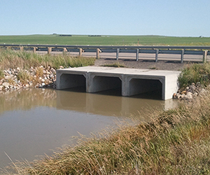
- Erosion control: Cast-in-place concrete wingwalls are usually built, even when the concrete box culvert is precast, to blend with the stream and create smoother flow transitions into and out of the box. Rock riprap is placed on each end to prevent erosion and long term maintenance.
Please feel free to comment and share your thoughts. I’d like to know how you do it, if there’s anything I’m missing or could be improved, or general comments.
Speak Your Mind